As its name suggests, CAD tools help us design stuff, normally in 3D. To explain why these kinds of tools are so useful, imagine the work of a person who designs airplanes, skyscrapers, or computers. These things are quite complex, and so drawing everything by hand, isn’t longer feasible.
Now, what if I told you that biology can also be designed? This is the art of synthetic biology, also called biological engineering.
Let’s take a look into how CAD is used in this field…
Engineering Biology
Just in case that you aren’t very familiar with synthetic biology, I definitely recommend that you check out this guide to it.
The reason we would want a software that designs biological stuff, is because in the XXI century, we want to standardize life. We want to better predict what cells will do, and overall we want to think of them more as computers rather than burritos.
If you agree with me, computers are logical. They are literally based off of things called logic gates. This means that they follow simple logic in which 0 will always be different from 1.
Just a few decades ago, we used to think that this didn’t happen with biology, just because of the innumerable amount of interactions that occur every single second. However, the rise of biological engineering has brought us to think the opposite.
Genetic circuits
Research on biological computing is still going on, and so talking about DNA logic gates is actually kind of impressive. Further in this article I’ll go over the tool that I used to design these logic gates.
For now, it’s important to understand how these actually work in the world of biology.
In this context, our inputs could be substances such as DNA, in the form of genes, and our outputs would be proteins. This means that if a certain gene is active, it could lead to the production of a certain protein, depending on the logic gate that we’re talking about.
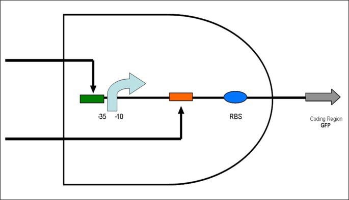
AND Gate
If the two inputs are true, the output will also be true.
Inputs: two small molecules called inducers
Inducers: controls the binding of the regulatory protein to the specific binding site on DNA
Operator part: DNA containing a protein-binding site
As of this specific image the specific components are:
Pale blue arrow: promoter
Orange rectangle: downstream operator part
Blue ellipse: a ribosome-binding site
Black arrows: environmental inputs
Gray arrow: coding region (output)
NOT Gate
The output is only produced in the absence of the repressor. Otherwise, the presence of the repressor obstructs the bound of RNAp and promoter.
Input: a repressor.
Repressor: DNA- or RNA-binding protein that inhibits the expression of one or more genes
Another explanation of this gate would be:
A NOT gate is a promoter that is turned on because of an environmental condition. This promoter then turns on an inhibitor, which inhibits another promoter, which would have activated a gene otherwise. In other words, when the input is 1 (first promoter is activated), then there will be no output (the last gene won’t be active)
A NOR gate would be a very similar one, only that if any of the two first promoters are activated, then the output will be 0.
Here are some examples of other logic gates:
Increasing complexity
Keep reading with a 7-day free trial
Subscribe to Biopunk to keep reading this post and get 7 days of free access to the full post archives.


